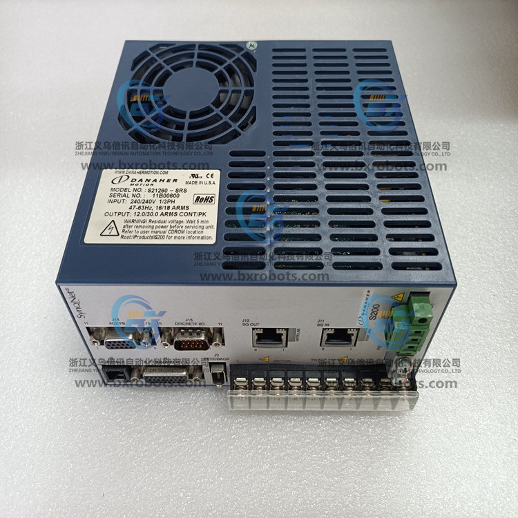
库卡 KRC4 伺服系统
在3线模式下,来自AIN4的引脚补偿激励电流也会流经3 kΩ返回电阻,在AIN0处产生一个附加电压:250 μA × 3 kΩ = 0.75 V。因此,AIN0处的总电压等于2.71 V + 0.75 V = 3.46 V,这违反了裕量要求。 所以,在3线模式下,各激励电流必须降至100 μA以提供足够的裕量。
In 3-wire mode, the pin-compensated excitation current from AIN4 also flows through the 3 kΩ return resistor, generating an additional voltage at AIN0: 250 μA × 3 kΩ = 0.75 V. Therefore, the total voltage at AIN0 equals 2.71 V + 0.75 V = 3.46 V, which violates the margin requirement. Therefore, in 3-wire mode, the individual excitation currents must be reduced to 100 μA to provide sufficient margin.
考虑30 V电压连接在AIN+和AIN-之间的情况。从AIN+朝里看,30V电压看到R1(3kΩ),之后是内部ESD保护二极管,再后面是从AIN3朝外看到的3kΩ电阻与从AIN4朝外看到的3 kΩ电阻并联。忽略内部ESD保护二极管,AIN+与AIN-之间的总电阻为3 kΩ + 3 kΩ|l3 kΩ=4.5 kΩ。因此,流经AD7124-4的电流限值为30V÷4.5 kΩ=6.7 mA。
Consider the case where the 30 V voltage is connected between AIN+ and AIN-. Looking in from AIN+, the 30 V voltage sees R1 (3 kΩ), followed by the internal ESD protection diode, and then followed by the 3 kΩ resistor seen from AIN3 facing out in parallel with the 3 kΩ resistor seen from AIN4 facing out. Ignoring the internal ESD protection diode, the total resistance between AIN+ and AIN- is 3 kΩ + 3 kΩ|l3 kΩ = 4.5 kΩ. Therefore, the current limit flowing through the AD7124-4 is 30V ÷ 4.5 kΩ = 6.7 mA.
所示电路可连接到2线、3线或4线RTD,大可测量3.92kΩ电阻,因此它适用于Pt100和Pt1000RTD。使用电流激励,电阻测量为RTD与3.92kΩ精密基准电阻(RREF)之间的比率式测量结果。所示,RTD测量在AIN1和AIN3之间进行,REFIN1+和REFIN1-用作测量的基准输入。线模式:仅AIN0上的激励有效,设置为250 μA,线模式:AIN0和AIN4上的激励电流均有效,各设置为100μA,线模式:仅AIN0上的激励有效,设置为250 μA。
The circuit shown can be connected to a 2-, 3- or 4-wire RTD and measures up to 3.92kΩ resistance, making it suitable for Pt100 and Pt1000 RTDs.Using current excitation, the resistance measurement is a ratiometric measurement between the RTD and a 3.92kΩ precision reference resistor (RREF). As shown, RTD measurements are made between AIN1 and AIN3, with REFIN1+ and REFIN1- used as reference inputs for the measurements. Line mode: Excitation on AIN0 only is valid and set to 250 μA,Line mode: Excitation current on both AIN0 and AIN4 is valid and set to 100 μA each,Line mode: Excitation on AIN0 only is valid and set to 250 μA.
